
An Inexpensive, On Camera, Laser Trajectory Device
H.W. “Rus” Ruslander, CSCSA, CLPE, CBPE, D-ABMDI
When teaching and using inexpensive laser pointers or torpedo lasers for trajectory analysis, I felt that there was a need to be able to mount the lasers so that the trajectory path could be photographed in a manner that represented the actual flight path of the projectile.
The photography of the light emitted by the lasers is usually done in either reduced lighting or darkness by either fogging the area the light passes through or, in a darkened area, holding a piece of white paper or cardboard and slowly walking along with the beam of light striking the paper. This is basically a long exposure which results in the appearance of a solid beam from the light source to the point of impact.
Some of the problems with using the paper are, once the path of the projectile goes above the reach of an average person, it is very difficult to continue showing the path using this method. Another problem encountered is trying to keep the laser’s beam on the paper. An issue with the fogging method, especially when outdoors, is that the fog dissipates rather quickly if there is a breeze. In an indoor scene, the fogging works well but the author has set off smoke detectors using it.
Another consideration is any health issues of the participants. Some people may be allergic to the chemicals used or experience an asthma-like reaction.
Generally, when doing a reconstruction using the lasers, the area is first photographed completely using proper lighting and photographic techniques from all angles. Then, the lasers are set up and the area is photographed again to show the placement of the devices.
The next step is to fog the area. Once the fog has reached a level to allow laser beams to become visible, they are photographed.
Cameras are tripod mounted, the auto focus turned off as well as the flash, and the camera focus is set on infinity. The area to be photographed is framed and if possible, a remote shutter release device is used. If a remote release device is not available, you can simply set the camera on a timed exposure setting, depress the shutter release and remove your hand. This will usually allow the camera to stop any shaking that touching it may have caused. The camera is set on either bulb or shutter priority and the ASA set at 1600 or as high as your camera will allow. The lights are now turned off and the scene is photographed as it appears once the lasers are turned on.
Photographs are generally taken from at least 3 different angles. One from the point of view of the shooter, one from the point of impact and one from either or both sides perpendicular to the beam of light. Next, a low level of light is turned on and the scene re-photographed. This will allow the recording of the background, and impact areas. This is very similar to photographing a luminal scene where a short burst of light is used at the end of the exposure to show the surface the reaction is on without washing out the luminal reaction itself.
In order to get a better photograph showing a view taken from the actual level of the laser beam, I decided to make a bracket that would mount onto the camera or tripod and hold the laser(s).
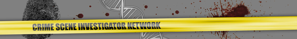
I purchased a 3’ piece of aluminum that is bent at a 90 degree angle and each side was 1” wide and cut it into 3 pieces, each 1’ long. I drilled a hole in the center of one side of the bracket. I also purchased a thumbscrew with 1/4x20 threads and threaded base that would slip over the bracket (figure 1).
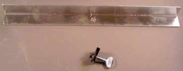
Figure 1
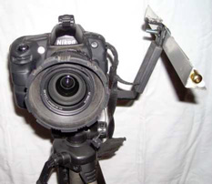
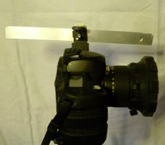
In addition, I also purchased a pack of Velcro tabs to use to secure the laser pointers to the piece of metal (figure 2, 3 and 4).
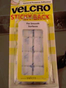
Figure 2
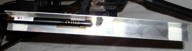
Figure 3
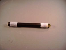
Figure 4
Using a bracket that is designed to mount a flash off to the side of a camera, I mounted the bracket and camera on the tripod. I adjusted the bracket so the lasers were along the same plane as the lens (figure 5 & 6).
The laser pointers are activated by depressing the momentary switch by using a spring paperclip.
With the area fogged, a photograph can now be taken that represents the sight path the shooter saw when he/she aimed the weapon at the target. The camera can then either be repositioned and a photograph taken for the viewpoint of the point of impact or, simply rotated 180 degrees and a photograph taken to show where the shooter had been when the shot was fired. By positioning the camera along the flight path and using 2 laser pointers, one facing in each direction, photographs can be taken showing both the point of impact and the area the shot was fired from (figure 7).
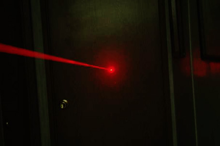
Figure 7
By introducing a second laser pointer, it can be demonstrated how 2 combatants were firing at each other. A green laser can be used so there is no question who was firing which shot. The victim and suspect would each be given a different color (figure 8).
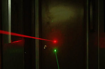
Figure 8
The total outlay for the 2 laser pointers and the hardware was approximately $36.00. The green laser pointers are now available on the internet, imported from Asia for about $15.00 each and the aluminum bracket and thumbscrew from the local hardware store for a total of less than $5.00. The spring clip used to hold sheets of paper together are easily obtained from your local office supply store and come in a variety of colors too. The camera bracket for positioning the flash off camera is available from most camera stores and costs between $16.00 and $60.00 depending on the type you select. I already had one so no additional cost was involved.
About the author:
Harold W. “Rus” Ruslander spent the first 23 years of his career as a Prince George’s County, Maryland Police Officer. That career included uniform patrol, special operations, administrative and investigative assignments.
After retiring, he moved to south Florida where he became a civilian crime scene investigator, first for the City of Lake Worth in March of 1993, and then for the Palm Beach County Sheriff’s Office from December 1996 until January 2003. He has been the Chief Investigator for the Palm Beach County, Florida Medical Examiner’s Office since January, 2003.
Mr. Ruslander’s’ accomplishments include being certified by the IAI as a Senior Crime Scene Analyst, a Certified Bloodstain Pattern Examiner and a Certified Latent Print Examiner as well as by the ABMDI as a Registered Medicolegal Death Investigator. In addition, he is Court recognized as a bloodstain pattern, latent fingerprint and crime scene reconstruction expert.
Mr. Ruslander has taught forensics at many locations throughout the United States and has designed numerous forty-hour classes and workshops. The Florida Department of Law Enforcement also certifies him as a law enforcement instructor.
Mr. Ruslander has written in excess of 20 forensic articles, which have been published in a number of forensic publications and various sites on the worldwide web. Mr. Ruslander has also made presentations and taught courses for the IAI Annual Training Conferences, the FDIAI Annual Training Conferences, The East Coast Armed Robbery Association, The Taylor Group, The Gold Coast Forensic Association, the Florida Chaplains Association and the Florida Fire Marshals Association, to name a few.
Mr. Ruslander is a member of the IAI, the FDIAI, the CBDIAI, FOP 89, FAME, ABMDI, IABPA, The American Legion, The Gold Coast Forensic Association and EPIC.